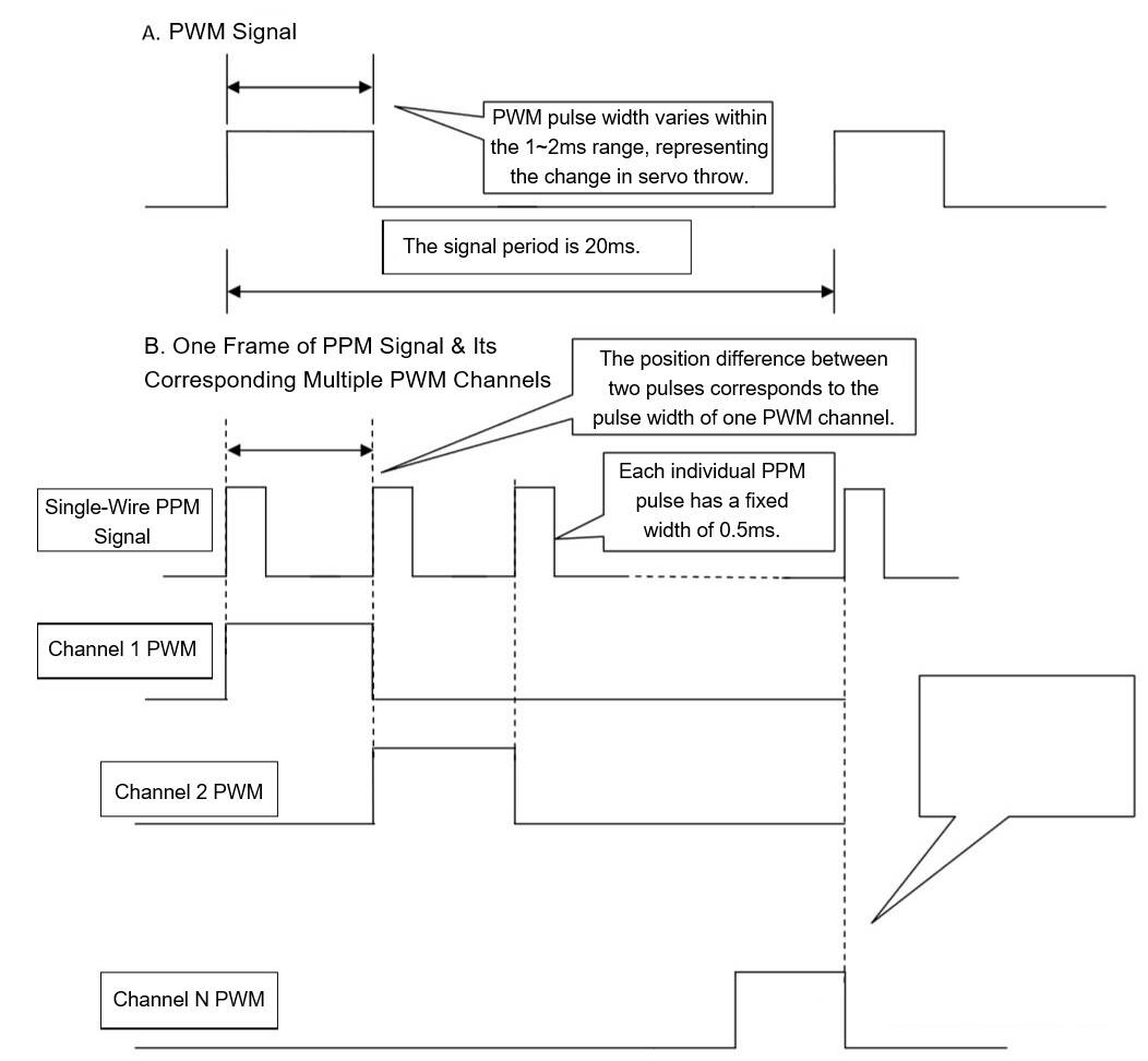
Explanation of PWM and PPM Signals
In radio-controlled models, the operation signals from the transmitter are wirelessly transmitted to the receiver. The receiver then connects to and controls actuators such as servos and electronic speed controllers (ESCs). Each actuator occupies one channel on the receiver. Each channel uses three wires: signal wire, positive power wire, and negative (ground) wire. The format of this signal is PWM (Pulse Width Modulation).
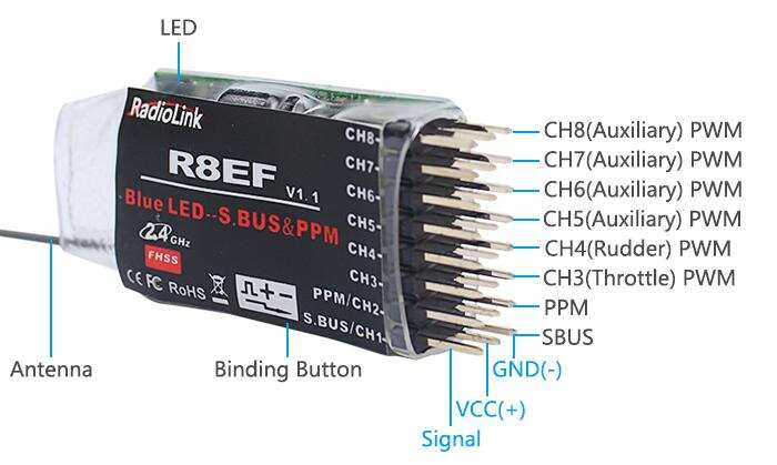
A PWM signal requires one wire per channel. Multiple channels require multiple wires. For applications needing multiple channels, such as connecting to a flight controller or a computer simulator, where multiple channels need to be transmitted through a single wire, PWM is not suitable. This led to the development of PPM (Pulse Position Modulation). (For an example, see the Radiolink R8EF 2.4G 8-channel receiver.)
The fundamental difference is that one wire can only transmit one channel with PWM, whereas one wire can transmit multiple channels with PPM. The diagram below helps illustrate this principle.